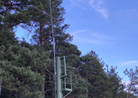
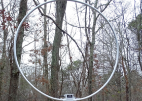
ALA1530LNP
The ALA1530LNP has a noise figure of approximately 0.2dB, which give a noise floor that is 13dB lower compared to a similar gain loop with a noise figure of 3dB.
This antenna together with the ALA1530LN are the only 1m dia. loops in production to use an ultra low noise JFET design. The loop has recently had a significant design change to improve LW/MW and SW reception. The antenna gain is increase by 9dB and the LW and MW signal to noise ratio s/n is up to 10dB higher, with an improved s/n on the HF bands. The LW and MW 3rd order IMD is now approx. 20dB lower when compared to the ALA1530 and the ALA1530S+. This being a combination of altering the gain distribution and the lower IMD of the JFETs. The antenna uses 8 very high gain JFETs in parallel push-pull with a Bipolar transistor cascode stage for extended bandwidth. A very low amplifier noise floor is achieved by dynamically decreasing the JFET Source resistance to a fraction of an Ohm. This is achieved using a proven technique developed in the 1980s by coupling the FET Gate to the source with a phase inverting transformer.
A unique 2 transformer push-pull Norton amplifier with a higher HF gain is now fitted in the antenna interface. MW OIP3 has been increased to +55dBm; thus giving this active antenna one of the highest third order intercept points in its class.
The amplifier is now housed in a separate module, thus isolating the electronics from the mechanical stress caused by wind loading on the loop. The amplifier module can be easily replaced in the unlikely event of a failure, without the customer having purchase a new loop antenna with the associated high shipping costs.
A re-settable fuse and a power on LED are now fitted to the antenna interface.
The loop antenna responds primarily to the Magnetic Field and rejects locally radiated Electric-Field noise providing far lower noise reception than active whip/dipole antennas. Compared to active whip/dipole antennas, the loop will reduce locally radiated noise by up to 30dB and mains borne noise by up to 60dB. The ALA 1530LNP has 30dB nulls to further reduce interference.
It is ideal for small gardens, indoors and directional reception using an antenna rotator.
ALA100
This antenna has recently been upgraded to extend the bandwidth from 10MHz to 30MHz. The amplifier gain has been increased to approx. 26dB; thus allowing for use with a smaller loop.
The Wellbrook Medium Aperture Loop ALA100LN is a specialist's antenna designed for the long wave, NDB band, medium wave and short wave DXer. The antenna is designed for a user-provided thin wire loop; 8-10m circumference. The ALA100LN has similar interference reduction properties as the ALA1530LN.
The Active Loop Antenna ALA100LN is a medium aperture antenna designed to provide improved performance compared to traditional active and passive antennas.
The new ALA100LN is the fourth generation of this antenna and uses 8 high gain low noise JFETs in parallel push-pull, cascode with the proven technique of coupling the FET gate to the Source with a phase inverting transformer resulting in a much lower amplifier noise floor. This lower amplifier noise floor is achieved by dynamically decreasing the JFET source resistance from approx. 10 Ohms to less than 1 Ohm.
The noise floor is approx. 7.0dB lower compared to other amplifier types with an equivalent 10m loop inductance.
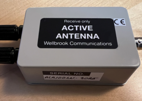
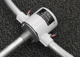
The ALA100LN Loop Antenna comprises of a loop/amplifier head unit together with an antenna interface.
RG58C 50 ohm coaxial feeder cable is recommended for the antenna. The maximum feeder length is 100m. The antenna interface feeds the 12 volt dc power to the antenna. The wire loop is provided by the user. This can be supported by a tree or light weight wooden poles 2-4m high spaced 2-5m apart. Alternatively the loop can be loft mounted or simply attached to the inside or outside wall of the home. However, for lower noise performance, the ALA100LN should be positioned away from sources of interference such as fluorescent lights, TVs, computers and electrical wiring. In most cases satisfactory results can be obtained by mounting the antenna near ground level and at least 6m from buildings.
The ALA100LN can also be mounted on to an antenna rotator using a simple 3m x 3m wooden frame to exploit the Loops directional characteristics. Alternatively an 10m circumference triangular loop can be used.


